Flowmeters & Semiconductor MFCs: Physics, Equations & Selection Guide
Selecting a flowmeter starts with the fluid and process duty, not the catalogue. Following the application-first reporting style used by industrial instrumentation leaders such as Honeywell Process Solutions, this guide pairs the governing physics of seven core flow technologies with schematic sketches, selection tables and practical rules of thumb.
1. Master Selection Matrix (Pros, Cons & Duty Fit)
| Technology | Measured Quantity | Typical Accuracy | Turndown | Pressure Drop | Key Pros | Key Cons | Best-Fit Applications |
|---|---|---|---|---|---|---|---|
| Electromagnetic | Volumetric ($Q$) | $\pm 0.2\text{–}0.5%$ of rate | $40:1$ to $100:1$ | Zero | No moving parts; handles slurries & corrosives; independent of density/viscosity | Requires conductive liquid ($\ge 1\text{–}5\ \mu\text{S/cm}$); fails on gases & hydrocarbons | Water, wastewater, chemical dosing, pulp & slurries |
| Vortex | Volumetric ($Q$) | $\pm 0.75\text{–}1.0%$ of rate | $10:1$ to $30:1$ | Low–Medium | Handles liquids, gases & steam; no moving parts; high $T/P$ rating | Fails at low $Re$ ($< 5{,}000\text{–}10{,}000$); sensitive to pipe vibration & straight-run needs | Saturated/superheated steam, compressed air, plant utilities |
| Ultrasonic (Transit-Time) | Volumetric ($Q$) | $\pm 0.5\text{–}2.0%$ of rate | Up to $250:1$ | Zero (clamp-on) | Non-invasive clamp-on option; no pipe cut or shutdown; bidirectional | Sensitive to bubbles, heavy solids & velocity profile; wall coupling matters | Large pipes, retrofits, HVAC, clean water & hydrocarbon checks |
| Rotameter (Variable Area) | Volumetric ($Q$) | $\pm 1\text{–}5%$ FS | $10:1$ | Constant (low–med) | Simple, zero power, local visual readout; low cost | Must mount vertically; sensitive to density/viscosity shifts; fragile if glass | Purge flows, lab benches, local sight-glass indication |
| Turbine | Volumetric ($Q$) | $\pm 0.25\text{–}0.5%$ of rate | $10:1$ to $20:1$ | Medium | Fast transient response; high repeatability; crisp pulse output | Moving bearings wear; requires clean, low-viscosity fluid & upstream strainer | Clean fuels, hydraulic test rigs, cryogenic liquids |
| Coriolis | Direct Mass ($\dot{m}$) & $\rho$ | $\pm 0.05\text{–}0.15%$ of rate | $> 100:1$ | Medium–High | Direct mass flow & density; unaffected by $P, T$ or viscosity; custody-transfer grade | High upfront cost; bulky above DN150; sensitive to two-phase gas entrainment | Custody transfer, precision batching, chemical reactors |
| Semiconductor MFC | Controlled Mass ($\dot{m}$) | $\pm 0.5\text{–}1.0%$ FS (or SP) | $50:1$ to $100:1$ | Controlled $\Delta P$ | Closed-loop sensing + PID valve in one body; ultra-clean all-metal seals | Gas-specific calibration ($c_p$); thermal types drift with ambient $T$ & mounting | CVD, ALD, plasma etch, epitaxy & gas-box delivery |
<!–more–>
2. Traditional Flowmeters: Physics, Equations & Sketches
2.1 Electromagnetic Flowmeter (Magmeter)
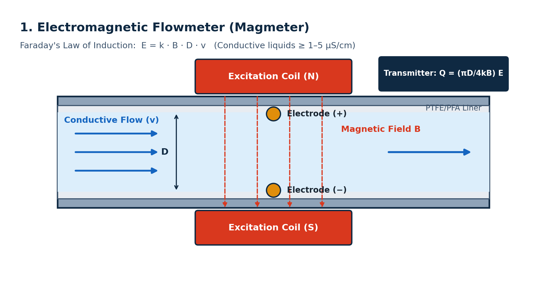
Foundation: Faraday’s law of electromagnetic induction. When a conductive liquid passes at mean velocity $v$ through a transverse magnetic field $B$ across a pipe of internal diameter $D$, an electromotive force $E$ is induced perpendicular to both the flow and the field:
$$E = k , B , D , v$$
Volumetric flow rate follows directly from pipe cross-sectional area:
$$Q = \frac{\pi D^2}{4} v = \frac{\pi D}{4 , k , B} E$$
where $k$ is a calibration geometry factor. Because $E$ depends only on $v$, the reading is independent of fluid density, viscosity, temperature and pressure—provided the flow profile is axisymmetric and electrical conductivity exceeds the meter threshold (typically $1\text{–}5\ \mu\text{S/cm}$, per Honeywell VersaFlow Mag).
2.2 Vortex Shedding Flowmeter
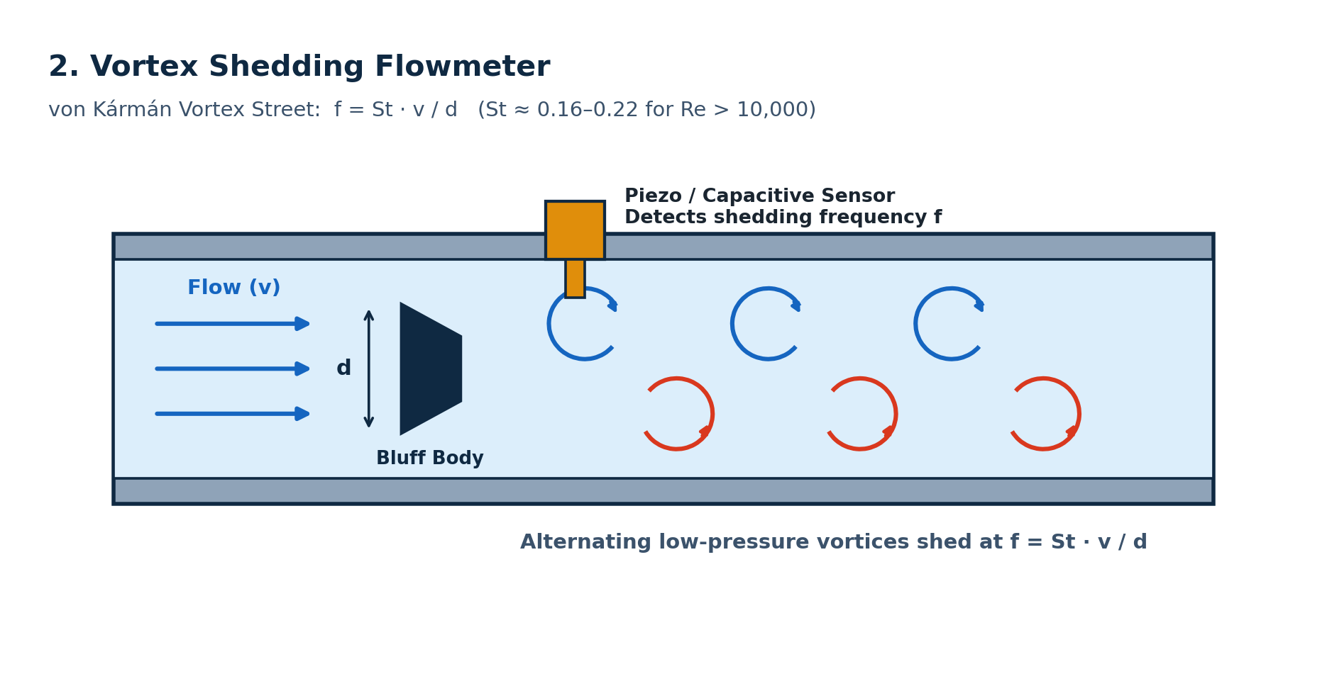
Foundation: von Kármán vortex street behind a non-streamlined bluff body of width $d$. Above a critical Reynolds number ($Re \gtrsim 5{,}000\text{–}10{,}000$), vortices shed alternately from each side at frequency $f$, governed by the dimensionless Strouhal number $St$:
$$St = \frac{f , d}{v} \implies v = \frac{f , d}{St}$$
Over the meter’s operating $Re$ plateau, $St$ remains nearly constant ($\approx 0.16\text{–}0.22$ depending on bluff-body geometry), making volumetric flow linear with shedding frequency:
$$Q = A_{\text{eff}} , v = \frac{A_{\text{eff}} , d}{St} f$$
A piezoelectric or capacitive sensor downstream detects the alternating pressure pulses.
2.3 Ultrasonic Flowmeter (Transit-Time & Doppler)
Foundation: Acoustic wave propagation superimposed on fluid velocity (Endress+Hauser).
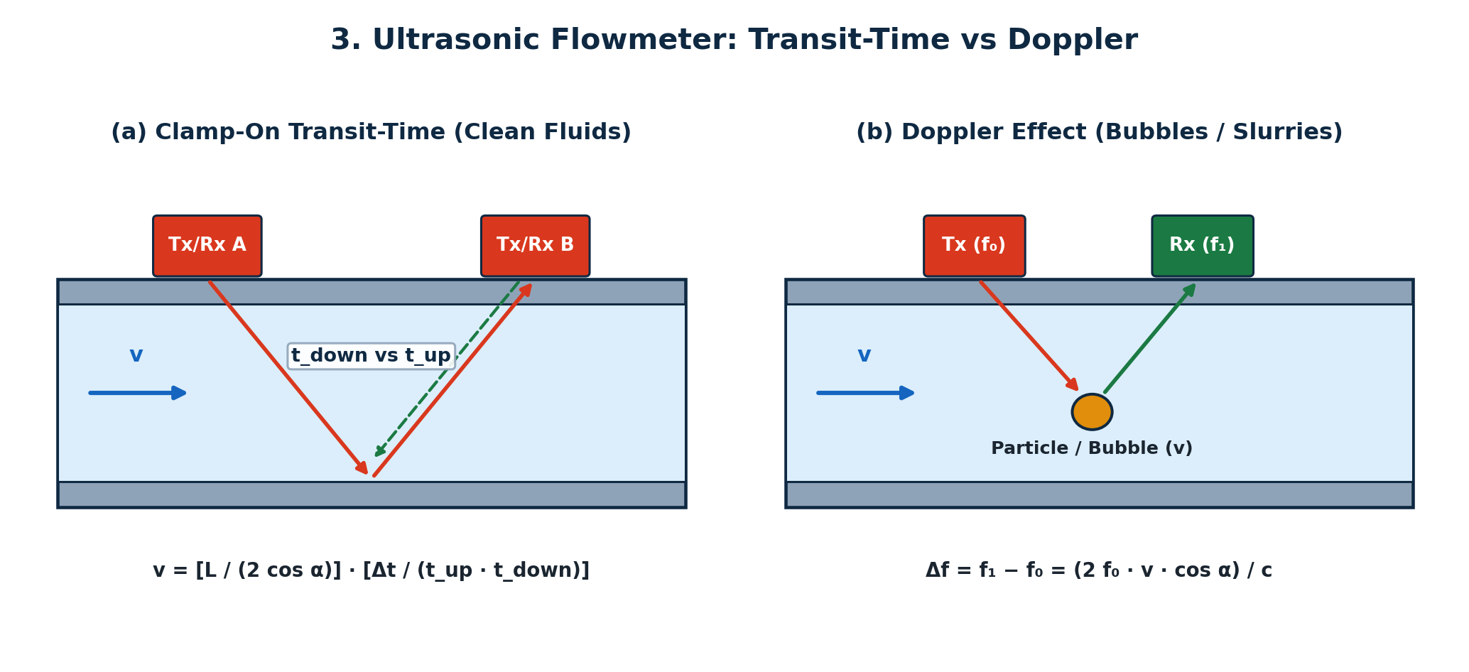
- Transit-Time (Clean Liquids & Gases): Two transducers separated by acoustic path length $L$ at angle $\alpha$ to the pipe axis exchange pulses alternately downstream ($t_{\text{down}}$) and upstream ($t_{\text{up}}$):
$$t_{\text{down}} = \frac{L}{c + v \cos\alpha}, \qquad t_{\text{up}} = \frac{L}{c - v \cos\alpha}$$
Solving for $v$ eliminates the fluid speed of sound $c$ (Soaring Instrument):
$$v = \frac{L}{2 \cos\alpha} \cdot \frac{\Delta t}{t_{\text{up}} , t_{\text{down}}}, \qquad \Delta t = t_{\text{up}} - t_{\text{down}}$$
- Doppler (Aerated Liquids & Slurries): Particles or bubbles moving at $v$ scatter an incident wave of frequency $f_0$, producing a Doppler shift $\Delta f$:
$$\Delta f = f_1 - f_0 = \frac{2 f_0 , v \cos\alpha}{c}$$
2.4 Rotameter (Variable Area Flowmeter)
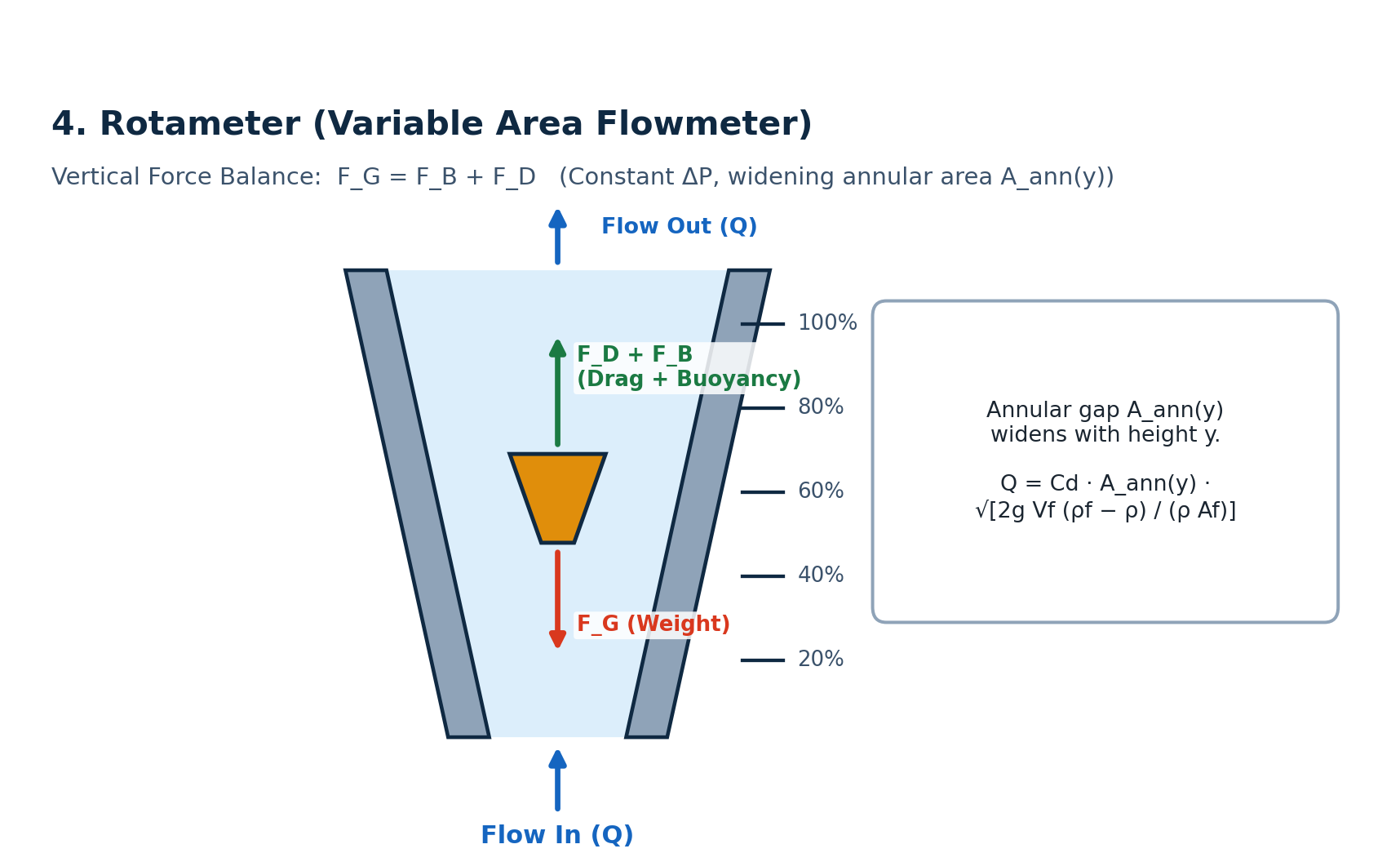
Foundation: Vertical force equilibrium on a float inside a tapered tube (Schwebekörper; DwyerOmega). As flow rises, the float ascends until the upward drag ($F_D$) and buoyancy ($F_B$) balance its weight ($F_G$):
$$F_G = F_B + F_D \implies \rho_f V_f g = \rho V_f g + \frac{1}{2} \rho v_{\text{ann}}^2 C_D A_f$$
Because the annular gap area $A_{\text{ann}}(y)$ widens with float height $y$, the pressure drop across the float stays nearly constant while velocity in the annulus scales as:
$$Q = C_d , A_{\text{ann}}(y) \sqrt{\frac{2 , g , V_f , (\rho_f - \rho)}{\rho , A_f}}$$
where $\rho_f, V_f, A_f$ are the float density, volume and frontal area, and $\rho$ is fluid density.
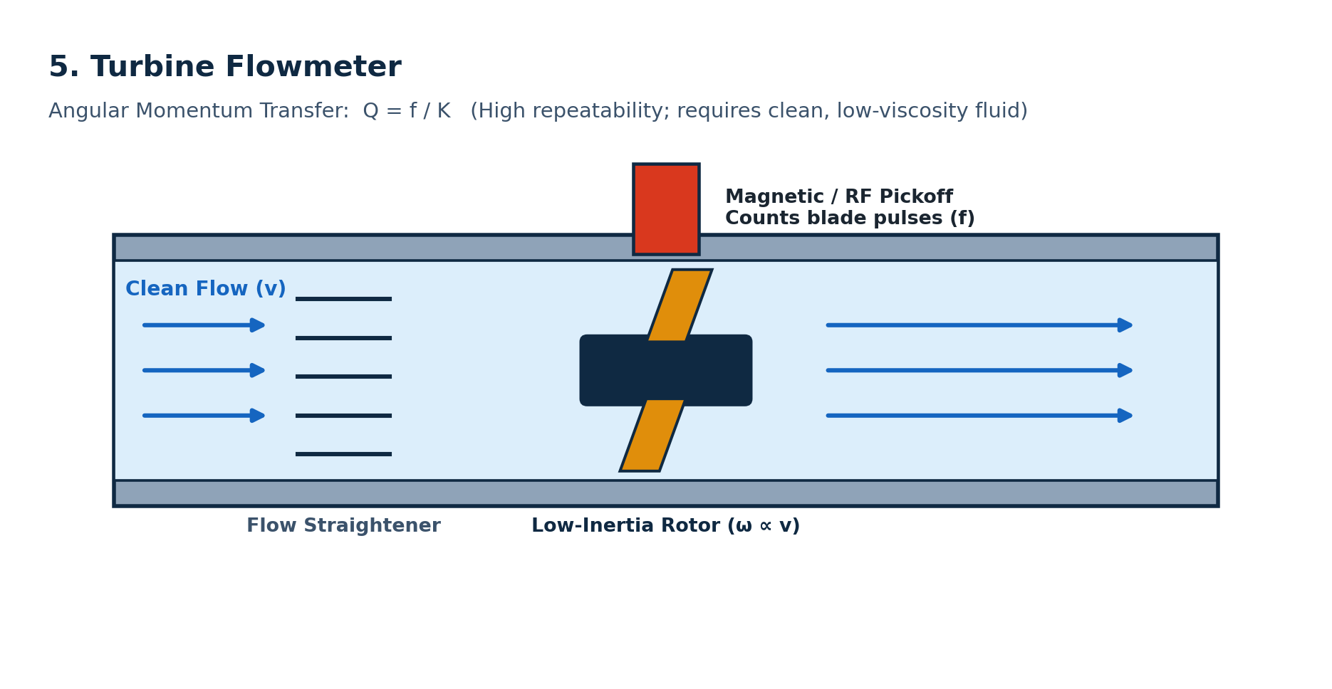
2.5 Turbine Flowmeter
Foundation: Angular momentum transfer from an axial fluid stream to a low-inertia bladed rotor (Webtec). Neglecting bearing friction and fluid drag, blade angular velocity $\omega$ is directly proportional to mean axial velocity $v$:
$$\omega = \frac{v \tan\beta}{r_{\text{eff}}}$$
where $\beta$ is the blade pitch angle and $r_{\text{eff}}$ is the effective pitch radius. A magnetic or RF pickoff coil counts blade passages at frequency $f$, giving volumetric flow via the meter’s calibrated K-factor (pulses per unit volume):
$$Q = \frac{f}{K}$$
At low flow rates, viscous drag and bearing friction cause $K$ to roll off non-linearly, setting the lower turndown limit.
2.6 Coriolis Mass Flowmeter
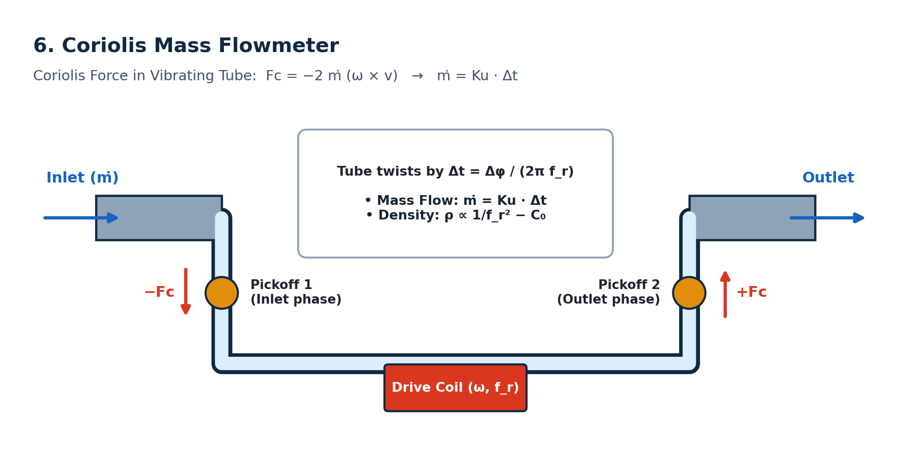
Foundation: Coriolis acceleration in a vibrating flow tube. A drive coil oscillates a U-shaped or straight tube at its natural resonant frequency $f_r$ ($\vec{\omega}$). Fluid moving at velocity $\vec{v}$ experiences an opposing Coriolis force on the inlet and outlet legs:
$$\vec{F}_c = -2 , \dot{m} , (\vec{\omega} \times \vec{v})$$
Because the forces act in opposite directions on the inlet and outlet limbs, the tube twists slightly during each half-cycle. Two optical or electromagnetic pickoffs measure the resulting phase difference $\Delta \phi$ or time delay $\Delta t$:
$$\dot{m} = K_u , \Delta t = K_u \frac{\Delta \phi}{2 \pi f_r}$$
Simultaneously, the tube’s resonant frequency shifts with the total vibrating mass (tube + fluid), yielding direct fluid density $\rho \propto 1/f_r^2 - C_0$.
3. Semiconductor Mass Flow Controllers (MFCs): What Happens Inside?
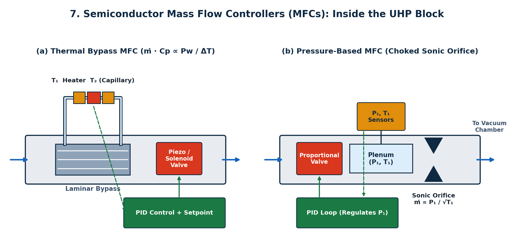
Unlike traditional industrial meters that only measure flow and leave regulation to an external PLC and control valve, a semiconductor MFC integrates sensing, closed-loop PID electronics and a fast proportional actuator (piezo or solenoid valve) inside a single ultra-high-purity (UHP) 316L VIM-VAR stainless-steel block (MKS Instruments; HORIBA).
3.1 Thermal MFC (Capillary Bypass & MEMS/CTA)
What happens inside:
- Laminar Flow Splitter (Bypass): Rather than heating the entire gas stream, a precision laminar-flow element forces a fixed fraction of gas through a thin heated capillary sensor tube while the bulk passes through parallel bypass channels.
- Heat Transfer Physics: Governed by the first law of thermodynamics and King’s Law, gas molecules carry heat downstream from an upstream heater/sensor coil ($T_1$) to a downstream coil ($T_2$). Over the linear capillary operating regime (MKS Instruments):
$$\dot{m} , c_p = a , \frac{P_w}{\Delta T} \quad \text{or} \quad \Delta T \propto \dot{m} , c_p$$
where $P_w$ is heater power, $c_p$ is specific heat capacity at constant pressure and $a$ is a geometry constant.
3. Closed-Loop Actuation: A Wheatstone bridge converts $\Delta T$ (or constant-temperature power $P_w$) into a voltage, which an onboard PID loop compares against the tool setpoint ($0\text{–}5\ \text{V}$, DeviceNet or EtherCAT) to modulate the control valve in $< 0.5\text{–}1\ \text{s}$.
Why it differs from traditional meters:
- Direct gas-property dependence ($c_p$, thermal conductivity) means switching from $\text{N}_2$ to $\text{CF}_4$ or $\text{SiH}_4$ requires a gas conversion factor or multi-gas calibration.
- Sensitive to upstream pressure transients (compressibility shifts the bypass split ratio) and mounting orientation (internal natural convection) unless pressure-compensated (MKS Instruments).
3.2 Pressure-Based MFC (PMFC)
What happens inside:
Used increasingly in modern etch and ALD tools where upstream gas-panel pressure fluctuates (Brooks Instrument), a PMFC places a precision critical-flow orifice (or laminar restrictor) downstream of the control valve and measures upstream pressure $P_1$ (and temperature $T_1$, plus downstream $P_2$ if unchoked). Under choked (sonic) conditions ($P_1 / P_2 \ge \left(\frac{\gamma + 1}{2}\right)^{\frac{\gamma}{\gamma - 1}}$):
$$\dot{m} = C_d , A_{\text{orifice}} , P_1 \sqrt{\frac{\gamma , M}{R , T_1} \left(\frac{2}{\gamma + 1}\right)^{\frac{\gamma + 1}{\gamma - 1}}}$$
Because mass flow depends only on $P_1$ and $T_1$, the valve actively regulates $P_1$ to hold $\dot{m}$ immune to downstream vacuum chamber pressure swings.
4. Engineering Rules of Thumb (Honeywell-Style Selection)
- Start with fluid phase and conductivity. Conductive liquid ($\ge 5\ \mu\text{S/cm}$)? Default to a magmeter for zero pressure loss and slurry tolerance. Non-conductive liquid, gas or steam? Move to vortex, ultrasonic or Coriolis.
- Check whether mass or volume actually drives your process. Chemical reactions, combustion, custody transfer and semiconductor deposition depend on moles/mass, not volume—use Coriolis (liquids/high-pressure gases) or an MFC (low-flow process gases).
- Respect turndown ratio at the minimum flow, not full scale. An instrument rated at $\pm 1%$ FS has $\pm 10%$ error at $10:1$ turndown (Environics). Always check uncertainty at your lowest operating setpoint.
- Never ignore straight-run and Reynolds-number limits. Vortex, turbine and single-path ultrasonic meters assume a developed velocity profile ($10\text{–}20D$ upstream). Coriolis and magmeters tolerate tighter piping.
- In semiconductor gas boxes, match the MFC architecture to upstream stability. Use thermal MFCs for ultra-low flows and clean steady supply lines; choose pressure-based MFCs where shared gas manifolds cause frequent upstream pressure spikes.
5. Quick Cheat Sheet
1 | • Magmeter E = k*B*D*v Conductive liquids only; zero ΔP |